Warning: All information Below is from the original manual
usage of the information is at own Risk
| Unpacking the Mainboard |
| Overview of Mainboard |
| Chapter 1 Easy Quick Jumper Settings |
| 1.1 CPU Speed Selection |
| 1.2 Other Jumper Settings |
| Chapter 2 Key Features |
| 2.1 Key Feature |
| Chapter 3 DRAM Installing |
| 3.1 DRAM Installing Table |
| Chapter 4 Award BIOS Setup Guide |
| 4.1 BIOS Setup |
| 4.1.1 Award BIOS Setup |
| 4.1.2 Main MENU Options |
| 4.1.2.1 Standard CMOS Setup |
| 4.1.2.2 BIOS Features Setup |
| 4.1.2.3 Chipset Features Setup |
| 4.1.2.4 Power Management Setup |
| 4.1.2.5 PCI Configuration Setup |
| 4.1.2.6 Load BIOS Defaults |
| 4.1.2.7 Load Setup Defaults |
| 4.1.2.8 Change Password |
| 4.1.2.9 IDE HDD Auto Detection |
| 4.1.2.10 SCSI Hard Disk Installation |
| 4.2 BIOS POST Error Codes |
| 4.2.1 POST Beep |
| 4.2.2 Error Messages |
| Chapter 5 VGA Installation |
| 5.1 SIS 6205 VGA Feature |
| 5.2 DOS Utility |
| 5.2.1 Install Program: INSTDRV.EXE |
| 5.2.2 SVGAUTIL.EXE |
| 5.2.3 Video Mode Table |
| 5.3 Software Drivers |
| 5.3.1 Windows 3.1 / 3.11 |
| 5.3.2 OS/2 3.0 (Warp) |
| 5.3.3 Autodesk ADI 4.2 - Protected Mode |
| 5.3.4 Wordperfect 5.1 |
| 5.3.5 GEM 3.0 / Ventura 2.0 |
| 5.3.6 PCAD 6.06 |
| 5.3.7 Versa CAD / 386 2.1 |
| 5.3.8 OrCAD Rel. 4 |
| 5.3.9 Lotus 2.x |
| 5.3.10 Windows NT 3.5 |
| 5.3.11 Windows 95 |
The JT586SV4 Mainboard comes packed in a sturdy cardboard shipping carton. The packing contains:
- The JT586SV4 Mainboard
- Diskette for VGA Driver and Enhanced IDE Device Drive
- This user manual
- Cable set for I/O Device
Note: Do not remove the mainboard from its original packing until ready to
The JT586SV4 Mainboard is easily damaged by static electricity. Observe the following precautions while unpacking and installing the mainboard
1. Touch an unpainted area of the system before handling the mainboard or any component. Doing so discharges the static charge user's body may have built.
2. Remove the mainboard from its anti-static wrapping and place it on a ground surface, component side up
3. Inspect the mainboard for damage. Shipping may have loosened components from their sockets. If any component appears loose, press carefully to seat it firmly in its socket
Do not apply power supply if the mainboard appears damaged. If ther is damage to the board, or items are missing, contact dealer immediately.
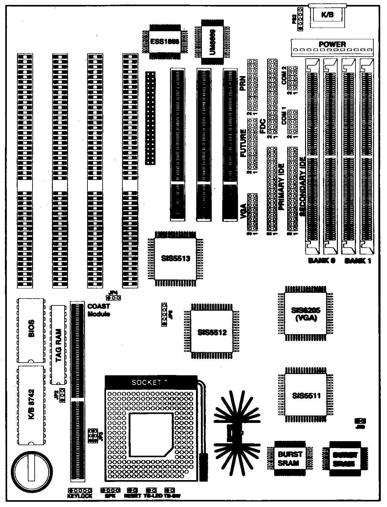
Note: Jumper (Shunt) convention of JT586SV4:
| Red | : Clock setting |
| Yellow | : Cache size setting |
| Black | : Others |
Chapter 1 Easy Quick Jumper Settings
For Intel CPU Jump Setting:
| Mhz | 200 | 180 | 166 | 150 | 133 | 120 | 100 | 90 | 75 |
| JP3 | 3-5 2-4 |
3-5 2-4 |
3-5 4-6 |
3-5 4-6 |
1-3 4-6 |
1-3 4-6 |
1-3 2-4 |
1-3 2-4 |
1-3 2-4 |
| JP5 | 2-3 | 4-5 | 2-3 | 4-5 | 2-3 | 4-5 | 2-3 | 4-5 | 1-2 |
For Cyrix 6x86 CPU Jump Setting:
| Mhz | 133 (P166) | 120 (P150) | 110 (P133) | 100 (P120) |
| JP3 | 1-3 4-6 |
1-3 4-6 |
1-3 4-6 |
1-3 4-6 |
| JP5 | 2-3 | 4-5 | 3-4 | 1-2 |
For AMD 5K86 CPU Jump Setting:
Mhz |
P75 | P90 |
| JP3 | 1-3 2-4 |
1-3 2-4 |
| JP5 | 1-2 | 4-5 |
| JP13 | 1-2 | 2-3 | JP9 | 1-2 | 2-3 | |
| P54C* | 3.3V | 3.45V | P55C | 2.9V | 2.5V* |
JP10. JP11, JP12 P54C / P55C Voltage select (* = default)
| JP10 | JP11 | JP12 | |
| P54C* | 1-2* | 1-2* | 1-2* |
| P55C | 2-3 | 2-3 | 2-3 |
* Default jump setting for P54C CPU
JP2 SRAM Size Setting
| 256K | 512K | |
JP2 |
2-3 |
1-2 |
Jumper Description
JP4 |
CMOS CLEAR (2-3) | J11 | PRINT PORT |
| J1 | KEY-LOCK | J12 | PRIMARY IDE |
| J2 | SPEAKER | J13 | FLOPPY CONNECTOR |
| J3 | HARDWARE RESET | J14 | PS/2 MOUSE |
| J4 | TURBO LED | J15 | SECONDARY IDE |
| J5 | TURBO SWITCH | J16 | COM1 |
| J7 | AUDIO CONNECTOR | J17 | COM2 |
| J9 | VGA CONNECTOR | J19 | POWER CONNECTOR |
| J10 | FEATURE CONNECTOR | J20 | HDD-LED |
CPU
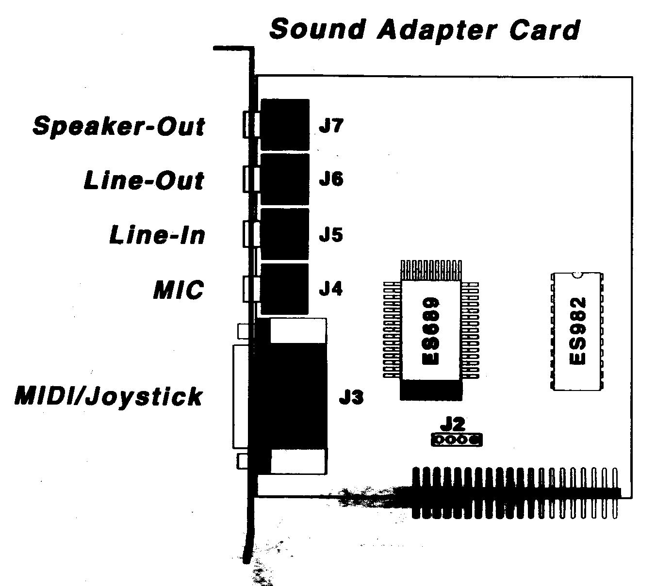
Sound (option)
Memory / Cache
Expansion Bus
I/O Devices
Software compatibility
BIOS