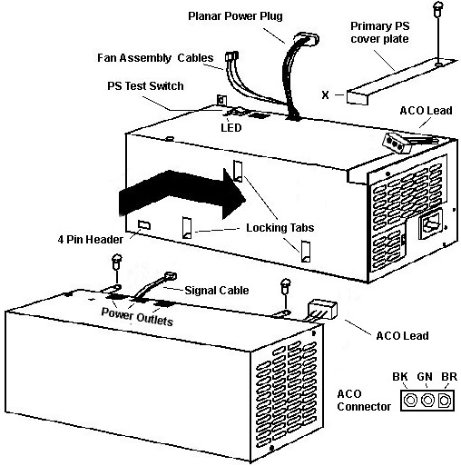
PC Server 500 (Type 86XX) Power Supplies
Connecting the 220W Power Supply Unplug the power cord!!! Remove the primary power supply cover plate retaining screw. Push the cover plate inwards until it stops (about 3/8 of an inch). Pull up on the edge now overhanging the side of the power supply. Note the tab and slot locking arrangement. Pull the ACO connector out of the power supply. It won't
come out very far, just enough for the plug body to clear the PS case.
DO NOT attempt to pull the ACO connector
cable out farther! The connector cable is short and it's tied to the power
supply frame as well. Connect the ACO connector from the 220W power
supply. Push both connectors back into the recess of the primary power
supply. Signal Cable From the 500 Man The signal cable from the 220W PSU plugs onto the four pin header on the side near the front of the primary 434W PSU. I imagine thats what turns on the 220W PSU. In short, plug the signal cable onto the four pin header in the main PSU. Slide the 220W power supply onto the locking tabs. Slide
it towards the rear of the system until it stops. Fasten the 220W PS to
the main PS with the two screws through the mounting tabs on the 220W
power supply. Re-Installing the primary power supply cover plate Caution
Rotate the cover plate so the downward part enters the recess first. Ensure that the locking tabs are in the slots. Push the cover forward until the cover plate mounting screw can be inserted. Fasten the cover down with a screw. When you rotate the cover, you may not be able to slide it far enough for the mounting screw hole in the plate to match up with the tapped hole in the power supply. Take a file and remove enough of the metal from the downward length on the side towards the exhaust end of the power supply. It is marked "X" in the illustration. You don't need to remove much. Main PS and Additional PS 220W Power Supply Unmasked! 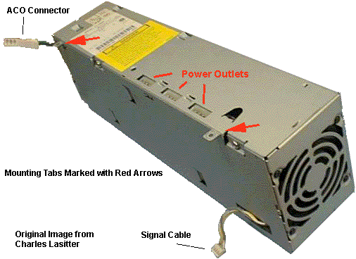
Primary Power Supply
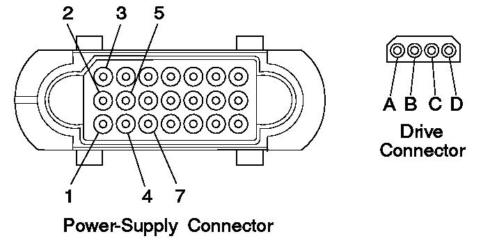
Voltages If the voltages are correct, and the power supply
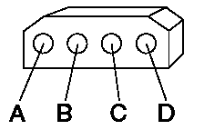
fan runs, the power supply is OK. _________________ __________________ _________________ _________________ | -Lead Pin | +Lead Pin | V dc Minimum | V dc Maximum | |_________________|__________________|_________________|_________________| | 5 | 3 | +3.7 | + 6.2 | | 5 | 4 | +9.0 | +15.0 | | 5 | 7 | -9.0 | -15.0 | | B | D | +3.7 | + 6.2 | | B | A | +9.0 | +15.0 | |_________________|__________________|_________________|_________________|
_________________ __________________ _________________ _________________
| -Lead Pin       | +Lead Pin        | V dc Minimum    | V dc Maximum    |
|_________________|__________________|_________________|_________________|
|     2           |     1            | +11.5           | +12.6           |
|_________________|__________________|_________________|_________________|
Optional Power Supply Drive Connector Voltages _________________ __________________ _________________ _________________ | -Lead Pin | +Lead Pin | V dc Minimum | V dc Maximum | |_________________|__________________|_________________|_________________| | B | D | + 3.7 | + 6.2 | | B | A | + 9.0 | +15.0 | |_________________|__________________|_________________|_________________|If the power supply shuts down, or appears to fail at power-on, you might have one of the following problems:
    ___ Caution ____________________________________________________________
   |                                                                        |
   | Unplug the power cord and wait two minutes before checking voltages to |
   | give the power supply capacitors time to discharge.                    |
   |                                                                        |
   |________________________________________________________________________|
© Copyright IBM Corp. 1995 |