
|
98.507 bytes |
Service Hints & Tips |
Document ID: DDSE-3QNJ77 |
PC Server 704 - Diskette / SCSI drive information
Applicable to: World-Wide
The following Diagram information is detailed below
1. Diskette Drive Tray
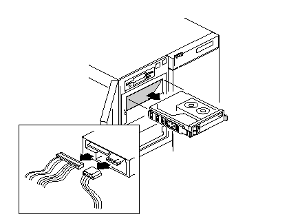
2. Drive (SCSI-2)
3. SCSI Drive Status LED Board
4. Drive Tray - 5.25 inch
5. Drive Tray - Hard Disk
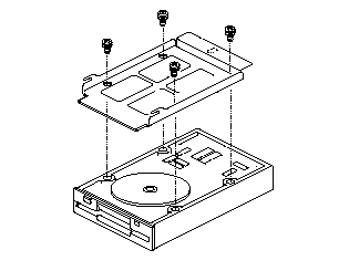
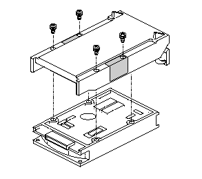
Diskette Drive (3.5-Inch)
Diskette Drive Tray
(Bottom View)
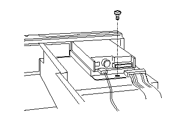
Drive (SCSI-2)
SCSI Drive Status LED Board
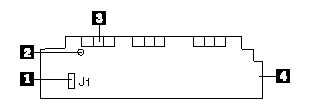
1. J1, cable to SCSI backplane
2. Hole for standoff
3. Status LEDs (three sets of three); insert board so these appear in slots in front EMI panel
4. End facing slot in center divider
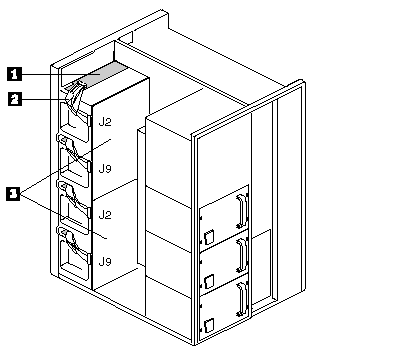
1. Status LED board (one board over each row of SCSI drives)
2. Cable form J1 on status LED board to J2 or J9 on SCSI backplane (one for each board)
3. SCSI backplanes, upper and lower
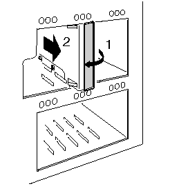
Drive Tray (5.25-Inch)
Drive Tray (Hard Disk)
(Bottom View)
|
Search Keywords |
| |
|
Hint Category |
Diskette Drives, Hardware Maintenance Information | |
|
Date Created |
19-06-96 | |
|
Last Updated |
29-10-98 | |
|
Revision Date |
22-10-99 | |
|
Brand |
IBM PC Server | |
|
Product Family |
PC Server 704 | |
|
Machine Type |
8650 | |
|
Model |
| |
|
TypeModel |
| |
|
Retain Tip (if applicable) |
| |
|
Reverse Doclinks |