
|
133.484 bytes |
Product Information |
Document ID: DDSE-42SV7L |
Netfinity 5000 - Bays
Applicable to: World-Wide
Bays
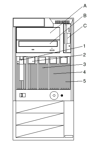
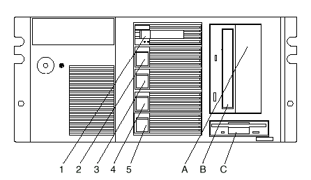
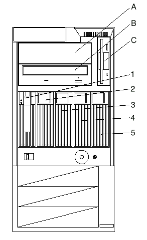
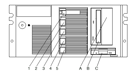
Internal drives are installed in bays. The bays are referred to as bay A, bay B, bay C, bay 1, bay 2, and so on.
The following illustrations show the locations of the bays in your server.
Tower model

Rack model

Your server comes with a CD-ROM drive installed in bay B and a diskette drive installed in bay C.
Table 1. Maximum Allowable Drive Sizes
|
Bay |
Drive Width |
Drive Type |
Drive Height |
|
A |
A 5.25-inch |
Removable media drive* only |
41.3 mm (1.6 in.) |
|
B |
5.25-inch |
CD-ROM |
41.3 mm (1.6 in.) |
|
C |
3.5-inch |
Diskette drive |
25.4 mm (1.0 in.) |
|
1 through 5 |
3.5-inch |
Hot-swap hard disk |
25.4 mm (1.0 in.) Slim line (SL) |
Notes:
* Removable media includes CD-ROMs, optical discs, and tapes. It does not include hard disk drives.
** A 41.3 mm drive installed in bays 1 through 5 will occupy two bays.
Types of Cables: Drives connect to your server with cables. Each cable connector is designed to fit a corresponding connector on a drive.
Three types of internal cables connect to the drives in your server:
- A four-wire power cable connects to each drive.
- A flat-ribbon signal cable connects to IDE devices.
One flat-ribbon cable connects the internal diskette drive.
The connector on one end of this cable attaches to the system board. The primary diskette drive installed in your server (usually known as drive A) is attached to the connector on the other end of this cable.
|
Note |
A second flat-ribbon cable connects the CD-ROM drive.
This cable has two drive connectors. A third connector attaches to the system board. The CD-ROM drive that comes with our server is attached to the connector on the end of this cable.
- Another cable connects internal SCSI devices. This SCSI cable has two connectors that connect to SCSI devices:
One to the backplane of the DASD hot-swap enclosure
One to a SCSI device you install in the open 5.25-inch bay
A third connector attaches to the SCSI connector on the system board.
External SCSI devices usually come with a SCSI cable. You attach one end of this SCSI cable to the SCSI connector on the back of the server, and the other end to the SCSI device. You usually can attach additional SCSI devices to this cable.
SCSI Devices: Your Netfinity 5000 supports drives that comply with American National Standards Institute (ANSI) SCSI Standards X3.131-1986 (SCSI), X3.131-1994, (SCSI-2), X3.277-1996 (SCSI-3 Fast-20 parallel interface), and X3.253-1995 (SCSI-3 parallel interface).
For a complete list of the SCSI devices supported on your Netfinity 5000, go to http://www.pc.ibm.com/support/ on the
World Wide Web.
If you install additional SCSI devices, you must set a unique identification (ID) for each SCSI device. This enables the SCSI controller to identify the devices and ensure that different devices do not attempt to transfer data at the same time.
|
Note |
SCSI IDs: If you install SCSI devices, you must set a unique identification (ID) for each SCSI device that you connect to your server. This enables the SCSI controller to identify the devices and ensure that different devices do not attempt to transfer data at the same time. The SCSI controller in your server supports SCSI IDs 0 to 5; ID 7 is reserved for the controller, ID 14 is reserved for the daughterboard (SAF-TE) on the DASD backplane. Use the SCSISelect Utility program to view the SCSI IDs
of SCSI devices in your server. (See Using the SCSISelect Utility Program for more information.)
|
Note |
If you install wide (16-bit) SCSI devices, you can set the IDs to any whole number between 0 and 6, or to any whole number between 8 and 13, or to 15. If you install narrow (8-bit) SCSI devices, you can set the IDs to any whole number between 0 and 6.
Your server automatically sets SCSI IDs for hot-swap hard disk drives, according to the jumper settings on the DASD backplane. Your server uses the hard disk drive SCSI IDs to send status information to the indicator lights on each hard disk drive. See Front Panel Indicators for the location and identification of the hard disk drive status lights.
Table 2 shows the default SCSI IDs that the backplane assigns for hot-swap hard disk drives.
Table 2. Automatically Assigned SCSI IDs
|
BAY |
1 |
2 |
3 |
4 |
5 |
|
ID |
0 |
1 |
2 |
3 |
4 |
Termination Requirements: The UltraSCSI controller and the backplane of the hot-swap bays provide termination for the internal SCSI bus (cable) in your server. There are no termination requirements for any SCSI devices you install in the hard disk drive bays or attach to this cable.
If you attach a SCSI cable and devices to the external SCSI connector, set the termination for the last device on that SCSI cable to Enabled. Refer to the instructions that come with the SCSI device for more information about termination.
Preinstallation Steps (All Bays)
|
Before you begin, be sure you have: |
Before you can install drives in your Netfinity 5000, you might need to perform certain preinstallation activities. Some of the steps are required only during the initial installation of an option.
1. Choose the bay in which you want to install the drive. (Refer to Table 1 for the drive types and sizes available for each bay.)
Tower model

Rack model

2. Touch the static-protective bag containing the drive to any unpainted metal surface on the server; then, remove the drive from the bag.
3. Check the instructions that come with the drive if you need to set any switches or jumpers on the drive, or if you need to attach a tray to the drive.
|
What to do next |
|
Search Keywords |
| |
|
Document Category |
Diagrams | |
|
Date Created |
03-12-98 | |
|
Last Updated |
03-12-98 | |
|
Revision Date |
03-12-99 | |
|
Brand |
IBM PC Server | |
|
Product Family |
Netfinity 5000 | |
|
Machine Type |
8659 | |
|
Model |
ALL | |
|
TypeModel |
| |
|
Retain Tip (if applicable) |
| |
|
Reverse Doclinks |