
|
27.203 bytes |
Service Hints & Tips |
Document ID: DDSE-3QNJGN |
PCServer704 - Front panel information
Applicable to: World-Wide
Front Panel Control Board
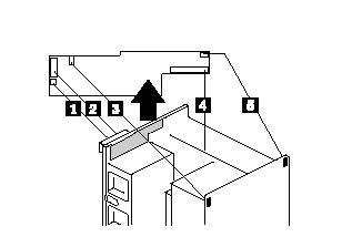
1. Remove the two screws. The board is now held in place bya pop-on/off snap.
2. Hold the board by the top edge or upper corners. Pull it slightly toward the back of the chassis to release the snaps. Carefully lift it up and out of the chassis.

1. J14, power cable to the liquid crystal display (LCD), 3-pin connector
2. J12, signal cable to the LCD 14-pin connector
3. J5, signal cable to intrusion switch at back corner above the power supplies, 3-pin connector
4. J11, signal cable to system board, 40-pin connector (pin 17 removed)
5. J2, signal cable to intrusion switch at back corner above board cage area, 3-pin connector
Front Panel Control Board Interface

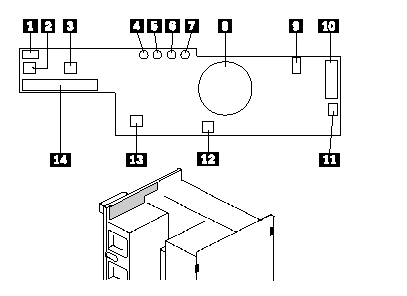
1. Signal from C2 switch at back edge near card cage 3-pin right-angle latching-style connector
2. Power switch
3. Reset switch
4. Power-on LED, green
5. Power-fail LED, amber
6. Cooling-fail LED, amber
7. Drive-fault LED, amber
8. Speaker
9. Signal from intrusion switch at back edge near power supplies 3-pin right-angle latching-style connector
10. Signal interface to the LCD 14-pin straight-head connector
11. Power to the LCD 3-pin straight-head connector latching-style connector
12. Hard drive bay C2 switch
13. NMI switch
14. Signal interface to system board 40-pin straight-head connector (pin 17 removed)
|
Search Keywords |
| |
|
Hint Category |
Hardware Maintenance Information | |
|
Date Created |
14-06-96 | |
|
Last Updated |
18-05-98 | |
|
Revision Date |
15-05-99 | |
|
Brand |
IBM PC Server | |
|
Product Family |
PC Server 704 | |
|
Machine Type |
8650 | |
|
Model |
| |
|
TypeModel |
| |
|
Retain Tip (if applicable) |
| |
|
Reverse Doclinks |