

|
306.783 bytes |
Service Hints & Tips |
Document ID: GSMH-3CGEGA |
|
This document is provided to IBM and our Business Partners to help sell and/or service IBM products. It is not to be distributed beyond that audience or used for any other purpose. |
IBM ValuePoint - Type 6384 system board
Applicable to: World-Wide
6384 325T System Board:
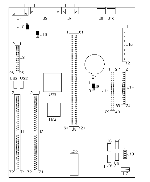
Figure 6. 6384 325T
6384 325T System Board:
|
B1 |
Battery |
|
J1 |
Memory-Module Socket 1 |
|
J2 |
Memory-Module Socket 0 |
|
J3 |
Video Feature Connector |
|
J4 |
Video Port |
|
J5 |
Parallel Port |
|
J6 |
Riser Connector |
|
J7 |
Serial Port |
|
J8 |
Password Bypass |
|
J9 |
Mouse Port |
|
J10 |
Keyboard Port |
|
J11 |
Hard Disk Connector |
|
J12 |
Beeper Bypass |
|
J13 |
Pins 1 and 2 - Power-On LED |
|
J14 |
Diskette Connector |
|
J15 |
Power Connector |
|
J16 |
IRQ9 |
|
J17 |
VGA Enable |
|
U5 |
512K X 9 System Memory |
|
U6 |
512K X 9 System Memory |
|
U8 |
512K X 9 System Memory |
|
U9 |
512K X 9 System Memory |
|
U20 |
BIOS |
|
U23 |
Math Coprocessor |
|
U24 |
386SLC Processor |
|
U32 |
256K X 16 Video Memory |
|
U33 |
256K X 16 Video Memory |
6384 425SX System Board:
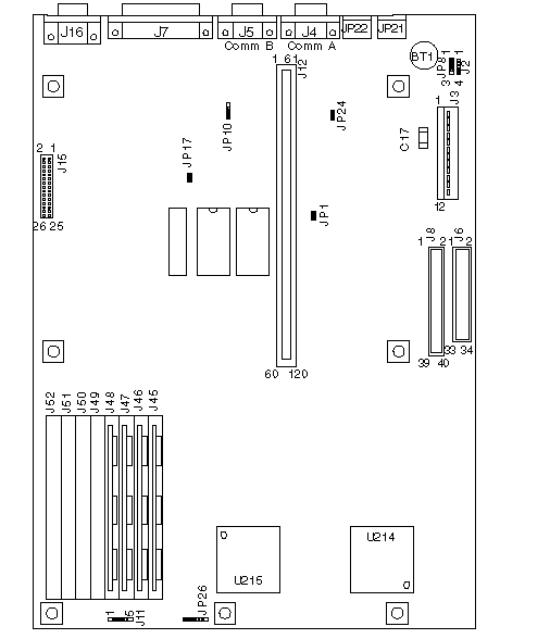
Figure 7. 6384 425SX
6384 425SX System Board:
|
BT1 |
Battery |
|
C17 |
Capacitor (Used with JP8 to erase password.) |
|
J2 |
External Battery |
|
J3 |
Power Connector |
|
J4 |
Serial Port (Comm A) |
|
J5 |
Serial Port (Comm B) |
|
J6 |
Diskette Connector |
|
J7 |
Parallel Port |
|
J8 |
Hard Disk Connector |
|
J11 |
Hard Disk LED (pin 4 and 5) |
|
J12 |
Riser Connector |
|
J15 |
Video Feature Connector |
|
J16 |
Video Port |
|
J45 |
Memory-Module Socket Bank 0, 0 |
|
J46 |
Memory-Module Socket Bank 0, 1 |
|
J47 |
Memory-Module Socket Bank 0, 2 |
|
J48 |
Memory-Module Socket Bank 0, 3 |
|
J49 |
Memory-Module Socket Bank 1, 0 |
|
J50 |
Memory-Module Socket Bank 1, 1 |
|
J51 |
Memory-Module Socket Bank 1, 2 |
|
J52 |
Memory-Module Socket Bank 1, 3 |
|
JP1 |
IRQ9 |
|
JP8 |
Battery Select |
|
JP10 |
VGA Enable |
|
JP17 |
VGA Enable |
|
JP21 |
Keyboard Port |
|
JP22 |
Mouse Port |
|
JP24 |
Mouse Enable |
|
JP26 |
Beeper Enable |
|
U214 |
487SX or 486DX2 |
|
U215 |
486SX Processor |
6384 433DX or 466DX2 System Board:
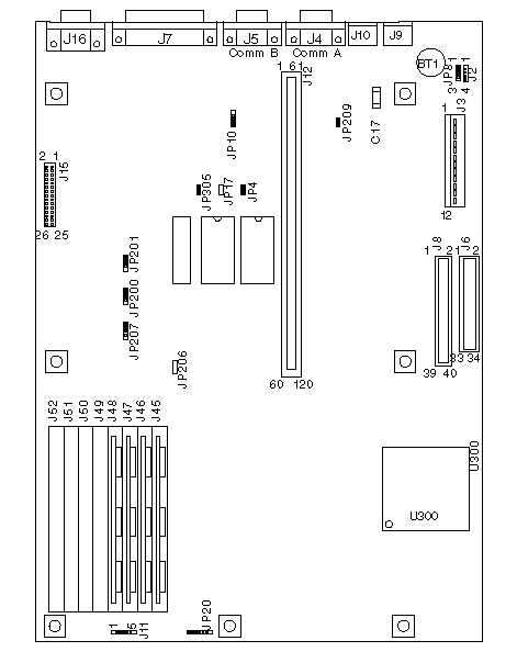
Figure 8. 6384 433DX or 466DX2
6384 433DX or 466DX2 System Board:
|
BT1 |
Battery |
|
C17 |
Capacitor (Used with JP8 to erase password.) |
|
J2 |
External Battery |
|
J3 |
Power Connector |
|
J4 |
Serial Port (Comm A) |
|
J5 |
Serial Port (Comm B) |
|
J6 |
Diskette Connector |
|
J7 |
Parallel Port |
|
J8 |
Hard Disk Connector |
|
J9 |
Keyboard Connector |
|
J10 |
Mouse Port |
|
J11 |
Hard Disk LED (pin 4 and 5) |
|
J12 |
Riser Connector |
|
J15 |
Video Feature Connector J16 Video Port |
|
J45 |
Memory-Module Socket Bank 0, 0 |
|
J46 |
Memory-Module Socket Bank 0, 1 |
|
J47 |
Memory-Module Socket Bank 0, 2 |
|
J48 |
Memory-Module Socket Bank 0, 3 |
|
J49 |
Memory-Module Socket Bank 1, 0 |
|
J50 |
Memory-Module Socket Bank 1, 1 |
|
J51 |
Memory-Module Socket Bank 1, 2 |
|
J52 |
Memory-Module Socket Bank 1, 3 |
|
JP4 |
BIOS Select |
|
JP8 |
Battery Select |
|
JP10 |
VGA Enable |
|
JP17 |
VGA Enable |
|
JP20 |
Beeper Enable |
|
JP200 |
Cache Configuration |
|
JP201 |
Cache Configuration |
|
JP206 |
Cache Configuration |
|
JP207 |
Cache Configuration |
|
JP209 |
Mouse Enable |
|
JP305 |
IRQ9 |
|
U300 |
486DX or 486DX2 Processor |
Note:
Jumpers should be set as shown.
6384 /D System Board (Type 1) (425SX, 433SX, 433DX, or 466DX2):
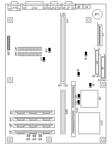
Figure 9. 6384 /D (Type 1)
6384 /D System Board (Type 1) (425SX, 433SX, 433DX, or 466DX2):
|
BT1 |
Battery |
|
J1 |
Power Connector |
|
J2 |
Diskette Connector |
|
J3 |
Hard Disk Connector |
|
J4 |
Keyboard Connector |
|
J5 |
BootBlock (not used: do not change) |
|
J6 |
Write Disable |
|
J7 |
Serial Port (Comm A) |
|
J8 |
Mouse Port |
|
J9 |
Password Bypass |
|
J10 |
Processor Upgrade |
|
J11 |
Processor Upgrade |
|
J12 |
Serial Port (Comm B) |
|
J13 |
Riser Connector |
|
J14 |
Parallel Port |
|
J15 |
Video Port |
|
J16 |
Monochrome Adapter |
|
J17 |
System Board Video Enable |
|
J18 |
Memory-Module Socket, MEM 1 |
|
J19 |
Memory-Module Socket, MEM 2 |
|
J20 |
Memory-Module Socket, MEM 3 |
|
J21 |
Memory-Module Socket, MEM 4 |
|
J23 |
Power-On LED |
|
J24 |
Hard Disk LED |
|
J25 |
Speaker |
|
J26 |
Video Feature Connector |
|
J47 |
Video Memory Connector |
|
J48 |
Video Memory Connector |
|
U9 |
486SX Processor |
|
U10 |
486DX or 486DX2 Processor Upgrade Socket |
|
U13 |
Cache Socket |
|
U25 |
Riser Connector Extension |
Note:
Jumpers should be set as shown.
6384 /D System Board (Type 2) (425SX, 433SX, 433DX, or 466DX2):
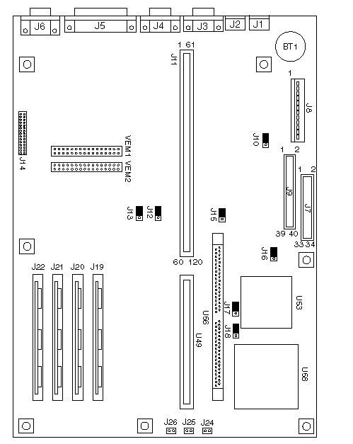
Figure 10. 6384 /D (Type 2)
6384 /D System Board (Type 2) (425SX, 433SX, 433DX, or 466DX2):
|
BT1 |
Battery |
|
J1 |
Keyboard Connector |
|
J2 |
Mouse Port |
|
J3 |
Serial Port (Comm A) |
|
J4 |
Serial Port (Comm B) |
|
J5 |
Parallel Port |
|
J6 |
Video Port |
|
J7 |
Hard Disk Connector |
|
J8 |
Power Connector |
|
J9 |
Diskette Connector |
|
J10 |
BootBlock (not used: do not change) |
|
J11 |
Riser Connector |
|
J12 |
Monochrome Adapter |
|
J13 |
System Board Video Enable |
|
J14 |
Video Feature Connector |
|
J15 |
Password Bypass |
|
J16 |
Write Disable |
|
J17 |
Processor Upgrade |
|
J18 |
Processor Upgrade |
|
J19 |
Memory-Module Socket, MEM 1 |
|
J20 |
Memory-Module Socket, MEM 2 |
|
J21 |
Memory-Module Socket, MEM 3 |
|
J22 |
Memory-Module Socket, MEM 4 |
|
J24 |
Power-On LED |
|
J25 |
Hard Disk LED |
|
J26 |
Speaker |
|
U49 |
Riser Connector Extension |
|
U53 |
486SX Processor |
|
U56 |
Cache Socket |
|
U58 |
486DX or 486DX2 Processor Upgrade Socket |
|
VEM1 |
Video Memory Connector |
|
VEM2 |
Video Memory Connector |
Note:
Jumpers should be set as shown.
6384 P60/D Pentium System Board:
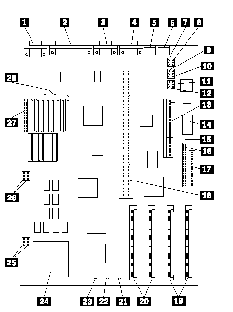
Figure 11. 6384 P60/D Pentium
6384 P60/D Pentium System Board:
|
1 |
Video Port |
|
2 |
Parallel Port |
|
3 |
Serial Port (Comm B) |
|
4 |
Serial Port (Comm A) |
|
5 |
Mouse Port |
|
6 |
Keyboard Port |
|
7 |
Monochrome/Color |
|
8 |
Setup (Reserved) |
|
9 |
CMOS Normal/Clear |
|
10 |
Password Bypass |
|
11 |
Program Write Protect |
|
12 |
FLASH Recover/Normal |
|
13 |
Power Supply Connectors |
|
14 |
Real-Time Clock |
|
15 |
PCI Power Connector |
|
16 |
Hard Disk Drive Connector |
|
17 |
Diskette Drive Connector |
|
18 |
Riser Connector |
|
19 |
Memory Module Connectors, Bank 0 |
|
20 |
Memory Module Connectors, Bank 1 |
|
21 |
Power-on LED |
|
22 |
Hard Disk LED |
|
23 |
Speaker |
|
24 |
Pentium Processor |
|
25 |
Fan Power Connectors |
|
26 |
66/60 MHz Jumper (Reserved) |
|
27 |
Video Feature Connector |
|
28 |
Video Memory Connectors |
|
Search Keywords |
| |
|
Hint Category |
Hardware Maintenance Information | |
|
Date Created |
18-12-96 | |
|
Last Updated |
30-04-98 | |
|
Revision Date |
05-01-99 | |
|
Brand |
IBM PC | |
|
Product Family |
ValuePoint | |
|
Machine Type |
6384 | |
|
Model |
various | |
|
TypeModel |
| |
|
Retain Tip (if applicable) |
| |
|
Reverse Doclinks |